A couple of weeks ago, I just post a review of my MCP23017 breakout board. As the board configuration allows to connect up to 8 of these boards, I decided to do it and see that it really works. My goal is interface 8 LCD displays with two wires: SDA and SCL from an I2C bus. With direct IO`s of a microcontroller, you need at least 48 lines to control all the displays. With this option (and a little of software, of course), you can do this with only two lines.
- The hardware
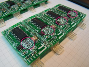
The first thing to do is mount the 8 boards. Schematics of the board is available here. Nothing new here, the only thing to consider at this time is to set the address of each board. This is done with the jumpers JP1 – JP3. For this components, I use a 0805 footprint in the PCB, so it’s esay to mount the 0 ohm resistors in the adequate position:
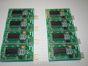
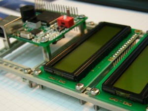
The eight boards assembled and ready to use
Resistors to set the address of each board
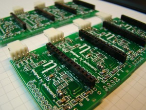
Top layer mounted
Also, I populated a 4-way polarized connector in order to prevent errors in the connection of the boards, avoid short-circuits between boards. The LCD used is the Winstar WH1602B-NYA-ET#, a standard 2×16 LCD, whit the only disadvantage that this model hasn’t backlight. In the manufacturer web, there’re some examples of code and schematics, including both 4 and 8 bits parallel mode.
- Boards connection
The most tedious task is to find and mount the 8 LCD’s. How or where I can mount it? Well, after thinking the form of do this, I used two backplane guides to mount all the displays. I use 2,5mm screws to fix it. The result is a bit unstable, but the global mount can handle easy:
Mounting detail
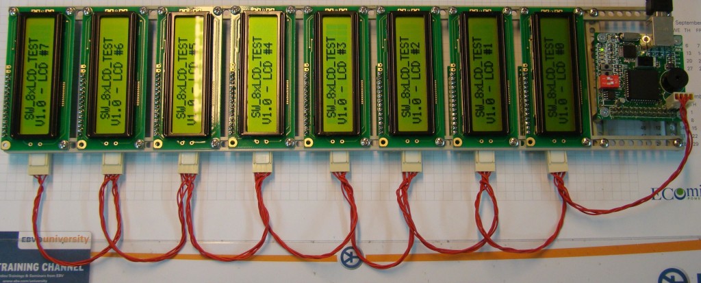
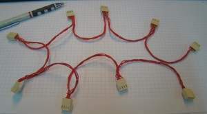
After half an hour, I finish the assemble of the 8 displays. Now, it’s time to make the wire to connect all. I use the housing connector that matches with the polarized ones, and makes a chain cable: in each connector, I crimp two wires (except in the first and in the last ones). Here is the result:
One wire to connect all!
Assembly completed, from the bottom layer
- The test software
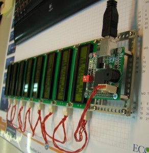
Like in my other projects, I use the DSETA CPU. It’s a generic board based on the AT89C51RE2 microcontroller, an 8051 core with a lot of peripherals from Atmel. This board has an I2C connector (software bus) to interface with I2C devices powered at 5V. So, with SDA and SCL (and, obviously, +5V and GND), I can connect the 8 LCD with this board. All the system is powered from the USB port, eliminating the need to have an external power source:
Connecting the CPU to the 8 LCD and power up with the USB port
I write the software in C for the Keil C51 compiler. The project is esay: I try to adapt the previous functions to manage the 8 devices. To do this, now all the related functions has a new parameter, that indicates the MCP23017 device that you want to use. First, the software initializes the 8 MCP23017 and, to ensure the initialization is correct, turns on both green and yellow leds on each board:
Green and yellow led’s indicating a correct initialization
Once that all the devices are initialized, it’s time to initialize each LCD. To do this, I use the LCD_init_I2C function, one time for each display. After, I show a message in each LCD to ensure they’re working OK. In the first line, all shows the same test string. In the second one, it appears the software version and the number of display (from 0 to 7). Here you can download the source code: SW_8xLCD_TEST. In a future entry, I try to develop an application where I can use this configuration to do something interesting. Any suggestion? 🙂



I think 48 lines is a little bit to many, you need only 10 lines to connect 8 displays.
If you connect D4-D7, RS and R/W to all the displays you need 6 lines.
Then add 3 address lines and the E line. This adds up to 10 lines.
That’s correct, with 10 lines you can do the same, working in 4-bit mode and adding a 3 to 8 decoder. But consider that each MCP23017 can manage up to 2 LCD in 4-bit mode, so if you want, with the same configuration you can manage up to 16 LCD displays with the same two lines!. Thanks for the comment, I” correct the number of lines you need to connect the 8 LCD displays
Pingback: » Comunicación entre microcontroladores – Bus I2C
Pingback: How to interface 8 LCD displays and 24 leds with only two wires | Arduino collector blog
Pingback: How to interface 8 LCD displays and 24 leds with only two wires | Make, Electronics projects, electronic Circuits, DIY projects, Microcontroller Projects - makeelectronic.com
Hey, I would like to ask you a few questions on this through email. please i seriously need the help. My email is jostynfr@gmail.com feel free to reply when possible. and thanks in advance
Very interesting project.
I have been trying to connect 6 LCD displays (1×16) to a AVR Mega8515. I use 4bit mode for the Lcds connecting D4, 5, 6 ,7 and R/S in a common bus to 5 outputs on the Mega8515 and the E from each Lcd to another 5 outputs. The R/W are all tied to ground and my software uses delays between the instructions.
However I have not been able to get all the Lcds to work. One works perfectly but the others show various errors, wrong characters, missing characters and one blank .
I think there maybe a problem using this bus idea. Perhaps I need some buffers/ line drivers.
Have you tried this method? If I can’t get it working I may use your method.
Any suggestions would be appreciated.
Hi Antony!
First of all, thanks for read the blog and for your comment! About your question, I don’t see any error in your approach (it’s difficult without references, schematics or source code!). Did you initialize all the LCD, one by one or all at the same time? You must do one by one, respecting the times for the inicialization on every LCD. About how you manage it on the SW side, I think the best way is make only one function to read and write on the LCD, and you pass as argument, the LCD you want to write. So, you only must debug one function for read and write, instead of one for each LCD. But, as I tell you, without code or schematics I can’t help you. Also, If you want more info about the method I use to drive all the LCD’s in the post, fell free to contact with me!
Hello Jechavarria,
Many thanks for your reply.
My SW does initialise all the Lcds at once. Each command is passed to a subroutine which sends it in two 4 bit parts to the bus pulsing all the E lines for each part. In between the commands are the required delays. I think all the Lcds are initialised – when I turn up the contrast control all 16 character matrices are visible (when they are Uninitialised on the first 8 matrices show).
You suggest that I should initialise each lcd in turn, I will try this but I don’t see why this is necessary especially as I am not reading from the Lcds.
I am already passing all the writes to the lcd through on subroutine. As this works for some of the Lcds I think it might be a hardware problem?
Hi Antony!
Sorry, maybe I don’t explain well, with the initialization I try to say that you must initialize one by one, not all at the same time. But for your comment, I think you just do this, so this will not the problem. You can check the hardware connections to ensure all is OK and all the LCD lines are well connected to the board. On the SW side, you can check one by one all the LCD’s. You will try to make a simple program that only sends info to only one LCD. Changing the LCD, you can test all the modules, and ensure that all works fine, and you can know if there’s a SW or HW problem. All these things are suppositions, as I tell you before, without schematics, datasheets or source code, I only can speculate about it!
Hello Jesus,
this is a very nice project! I have also experimented with port expanders but then opted for the use of cheap Microcontrollers (ATtiny2313 / PIC16F54). These offer at slightly lower cost the advantage of MC. You can store predefined texts in RAM, use virtual addresses to multiple displays react simultaneously and much else.
Hello Martin,
I’m very interested in your project. I have not managed to run 8 Lcds from a mega8515 and I think the main problem has been long leads to the lcd units. I have tried terminating resistors on the data lines which helps but it is not 100% relatable. If I had a ATtiny2313 mounted on the back of each lcd this might be a good solution. Do you use SPI or UART to transmit the data? Would this work over wires about 0.5m ?
Antony
Hi Antony,
my solution provides to use a microcontroller for each display. I usually use UART for data transport, rarely I2C. At the moment I am experimenting with LIN. This protocol supports virtual addresses. thus can be addressed multiple displays simultaneously. But the protocol is not critical, since as a user interface displays require only low data rates. People can not read displays very quickly. A very early prototype you can see here: http://www.elfri.de/?p=9
This prototype uses an Atmega168 and is Arduino compatible. This is obviously overkill, even the quartz is not necessary, since you can syncronize with the LIN data transmission.